If you’ve ever had an electrician run tests after a new installation or during a periodic inspection, there’s a good chance a loop impedance test was part of the job. Most people walk past this step without a second thought — and honestly, that’s fine. That’s what professionals are for. But understanding what the test actually does? That’s worth five minutes of your time.
Let’s break it down properly.
What Is a Loop Impedance Test?
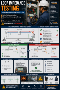
A loop impedance test measures the total resistance in the fault current path — the route electricity would travel if something went seriously wrong in your installation.
Think of it this way. Electricity flows from the supply transformer, through your wiring, and back again in a continuous loop. When a fault happens — say, a live wire touches an exposed metal casing — fault current rushes through that same loop, trying to get back to earth. The question is: does it get there fast enough to trip your circuit breaker?
That’s exactly what this test answers.
The earth fault loop impedance (Zs) represents the total impedance of the complete fault current path — from the source, through the line conductor to the fault, and returning via the protective conductor and earth path. If Zs is too high, the fault current will be too low to trip the protective device within the required time.
In plain terms: high impedance = slow disconnection = danger.
Why Should You Care?
Because the consequences of skipping this test aren’t minor. They’re fires, electric shocks, and damaged equipment.
Earth loop impedance testing is essential because if a live conductor accidentally connects to an earth conductor in a faulty appliance or circuit, the resulting short-circuit current to earth can easily be high enough to cause electric shock or generate enough heat to start a fire.
Your circuit breaker or fuse is the safety net here. But that safety net only works if it can react quickly enough. A loop impedance test ensures your breakers or fuses will trip within the safety time limits during a fault, preventing electric shock or fire hazards.
A high impedance reading isn’t just a number on paper — it’s a warning that something is wrong. It can indicate loose terminations, corroded contacts, or undersized conductors that could lead to voltage drops and overheating.
know more about – Elion’s Successful Electrical Safety Audit in Bhiwadi, Rajasthan
The Two Key Values: Ze and Zs
This is where many people get confused, so let’s be clear.
There are two measurements involved in loop impedance testing, and they are not the same thing.
Ze is the external earth fault loop impedance. This is the impedance that comes from the supply network — the part you don’t control. Ze is measured at the origin of the installation with the main earthing conductor disconnected. It represents the impedance of the supply network only.
Zs is the total earth fault loop impedance — the full picture. Zs is measured at each point on a circuit and includes Ze plus the resistance of the circuit line conductor (R1) and the CPC (R2). The relationship is: Zs = Ze + R1 + R2.
Both values matter. Ze tells you what the supply network contributes. Zs confirms whether the complete installed circuit — from supply to socket to earth — will behave safely under fault conditions.
How the Test Is Actually Performed
The process isn’t complicated, but it does require trained personnel and the right equipment.
The testing procedure starts with adequate circuit separation and the use of a voltage meter to ensure that the circuit is completely de-energised. The electrician visually inspects the circuit for visible faults such as damaged conductors or loose connections which could alter the results.
After that, a dedicated loop impedance tester (or multifunction installation tester) is connected. The tester injects a known current into the circuit and measures the resulting voltage drop, calculating the impedance from Ohm’s law.
There are two common test current levels used in practice:
With a test current of approximately 23A where circuits are protected by overcurrent devices such as fuses or circuit breakers only; or with a test current of approximately 15mA to prevent unwanted tripping where circuits are protected by 30mA or other RCDs.
Why the lower current for RCD circuits? Because injecting 23A through a 30mA RCD would trip it immediately. The low-current method avoids that — though it does come with slightly lower measurement resolution.
Where Does the Loop Impedance Test Fit in the Testing Sequence?
It doesn’t happen in isolation. BS 7671 Regulations 643.2 to 643.11 specify that tests must be carried out in a particular sequence. This is not optional — the order matters because later tests depend on the results of earlier ones.
The full sequence is:
- Continuity of protective conductors
- Continuity of ring final circuit conductors
- Insulation resistance
- Polarity
- Earth fault loop impedance (Ze and Zs)
- Prospective fault current
- RCD performance
- Functional testing
The loop impedance test sits fifth in that list for good reason. You need to confirm continuity and insulation integrity first — otherwise your impedance results won’t mean much.
Pass and Fail: What Do the Numbers Mean?
Here’s where it gets practical.
BS 7671:2018+A3 specifies a fundamental requirement for TN systems: Zs × Ia ≤ Uo — where Zs is earth fault loop impedance, Ia is the current causing automatic disconnection within the required time, and Uo is the nominal line-to-earth voltage.
For a common example: a 32A Type B MCB at 230V with a 0.4-second disconnection time has a maximum Zs of 1.44 ohms. Maximum values for each device type and rating are published in BS 7671 Tables 41.2 to 41.6.
But here’s the catch most people miss — temperature.
Conductor resistance increases with temperature. At maximum operating temperature for PVC-insulated cables (70°C), resistance is approximately 20% higher than at ambient temperature (20°C) at which testing is performed. This means field-measured values must be compared against adjusted limits rather than the raw tabulated Zs figures in BS 7671.
The highest measured Zs value for each circuit should not exceed 0.8 of the relevant value in the BS 7671 tables. In other words, select the appropriate value from the tables and multiply it by 0.8.
So if your table says 1.44 ohms, your measured result must come in at or below 1.15 ohms. That 20% headroom accounts for the real-world temperature increase during normal operation.
What Happens When the Test Fails?
A failed loop impedance test means the protective device cannot guarantee safe disconnection within the required time. That’s not something you can overlook.
Common causes include:
- Corroded or loose connections — adding resistance at joints
- Undersized conductors — too thin for the circuit length
- Damaged protective conductors — broken earth paths mid-circuit
- Excessive cable runs — long circuits naturally accumulate resistance
Loop impedance testing helps identify potential faults in the circuit such as high resistance connections, damaged conductors, or faulty protective devices. These faults can compromise the safety and performance of the electrical installation, and timely detection allows for necessary repairs or replacements.
Fixing a failed test usually means addressing the root cause — tightening connections, replacing conductors, or in some cases, adding RCD protection (which allows a higher Zs limit because the RCD operates on leakage current rather than fault current magnitude).
Earthing System Type Changes Everything
Not all installations are the same. The earthing system determines what loop impedance values are realistic — and what protection strategy is required.
TN-C-S (PME) systems typically produce Ze values of 0.35 Ω or less, resulting in high prospective fault currents and fast disconnection times. TN-S systems provide a dedicated protective earth conductor with moderate, predictable Ze. TT systems, where the return path for fault current passes through the soil, commonly have Ze values of tens or hundreds of ohms — at which point overcurrent devices alone cannot achieve the required disconnection time, making RCD protection mandatory.
For TT systems specifically, the compliance check shifts from a simple Zs table lookup to a formula: RA × IΔn ≤ 50V — where RA is the earth electrode resistance and IΔn is the RCD’s rated residual operating current. The 50V limit represents the maximum safe touch voltage.
The Regulatory Framework
The loop impedance test isn’t a recommendation — it’s a requirement.
BS 7671 (IET Wiring Regulations), IEC 60364, and NFPA 70 (NEC) all require loop impedance verification, because insufficient fault protection has historically resulted in countless electrical accidents, fires, and fatalities.
IEC 60364 specifies requirements for fixed electrical installations in buildings, including verification of protection by automatic supply disconnection. Measurement of earth loop impedance and determining the Prospective Fault Current (PFC) are critical for safety and form integral parts of the International Electrotechnical Commission’s guidelines.
In India, the loop impedance test aligns with IS 732 (Code of Practice for Electrical Wiring Installations), which draws on the same fundamental principle: protective devices must disconnect fast enough to prevent harm.
How Often Should the Test Be Done?
Testing isn’t a one-time event. Electrical installations age, connections loosen, and conductors degrade.
Regular loop impedance testing is crucial for identifying any changes or degradation in the electrical system. For commercial and industrial premises, periodic inspection and testing intervals vary by risk category. High-risk environments — hospitals, factories, petrol stations — warrant shorter intervals than a standard office building.
As a general benchmark, the IET Guidance Note 3 recommends:
- New installations — tested at completion before handover
- Commercial premises — every 5 years
- Industrial premises — every 3 years
- High-risk environments — every 1 year or less
Always confirm the applicable schedule with a qualified electrical inspector, since local regulations and insurance requirements may set stricter timelines.
Final Thought
The loop impedance test is one of those things that works quietly in the background — until it doesn’t, and then it’s the only thing standing between you and a serious electrical incident.
It confirms that your protective devices will actually protect you. It catches problems before they become disasters. And it gives you documented proof that the installation meets the safety standards required by law.
For anyone managing a building, commissioning a new electrical installation, or simply trying to understand what happens during an electrical inspection — this test is not optional, and it’s not a formality. It’s the check that makes everything else trustworthy.
This article references BS 7671:2018+A3 (IET Wiring Regulations), IEC 60364, and guidance from the IET On-Site Guide and Electrical Safety First. For installation-specific advice, always consult a qualified electrical professional.